Andrew Gregory's Web Pages
![]()
Sunset at Walganna Rock, 27°23'54"S 117°28'9"E
 Remote Control
2002-07-12: I've recently learned that Oatley will sell the UHF receiver module separately. It doesn't need a separate decoder chip, which simplifies the design of the receiver a little.
2002-05-24: Oatley Electronics have recently announced a new series of UHF remote control parts, including keyfob transmitter and receiver kits! I have yet to receive a reply from Oatley as to whether they can supply just the radio receiver module without needing to get a complex additional PCB for relays and other bits that aren't necessary for the camera remote control. Prices are also yet to be determined. I will also have to redesign the receiver PCB I had done for the earlier series of remote controls.
2002-03-10: Unfortunately, Oatley Electronics have discontinued their UHF keyfob transmitter. For this reason, I cannot recommend anyone attempt to build a remote using my instructions. It also means that my plans for making kits and finished versions for sale cannot be carried through. However, Oatley have not discontinued their UHF data transmitter, nor the UHF receiver board. This leaves open the possibility of creating my own receiver/transmitter (and maybe replace those hard to find encoder/decoder ICs with PICs). However, this is fairly complicated and time-consuming, so it could be many months before anything is ready.
After I bought my Casio, I started hearing about the fun Olympus and Canon owners were having with their remote controls. Casio had not released any remote control for the QV-3000 (they have since released one for the QV-2800 that also works for the QV-3000) so I had to make my own.
I started out by looking at infra-red remote controls. I went as far as buying a kit IR receiver/transmitter and BASIC Stamp, but I was having troubles designing a workable keypad for the transmitter side. Then I found a UHF remote control kit at Oatley Electronics. The transmitter comes in a very nice and small keyfob package. The receiver is a fully integrated and pre-tuned board with a raw data output requiring only a complementary decoder chip to match the encoder chip in the transmitter.
I initially prototyped a design using the BASIC Stamp and radio parts. Construction of the Mk1 Receiver describes this initial attempt. The main problem is that the Stamp is very expensive, and the project uses less than 10% of it's capacity! All up, the Mk1 project costs about AUD$166 to build.
My second design uses the Microchip 12C508 PIC chip. This is much cheaper than the Stamp, but can only be programmed once! The total cost of the Mk2 is about AUD$60.
If you're interested in a remote control that's actually available for sale (unlike mine right now), see Wireless remote control for Casio QV-3000.
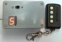
The remote control works by dividing the possible camera functions into groups, or modes. This is the only way to fit the 15 camera buttons into the four provided by the transmitter. Buttons on the transmitter are numbered 1 to 4, starting with the one closest to the LED. Pressing button 4 advances through the modes. The function of the remaining buttons depends on the mode. The decimal point lights up each time a button is pressed.
| LED display | Mode name | Button 1 | Button 2 | Button 3 |
|---|---|---|---|---|
| Shutter | Take photo | Focus lock | ||
| Timer/Tele | Timer mode | Telephoto | Wide angle | |
| Program | Mode | +/Right | Set | |
| meNu | Menu | Down | Set | |
| Display | Preview | Disp | ||
| Lighting | Flash mode | Up | Down | |
| Focussing | Focus mode | -/Left | +/Right |
These can be easily changed in the source code by modifying the 'mode table'. If you add or remove modes, make sure the 'number of modes' constant is updated.
The transmitter is a four button key fob type supplied in kit form by Oatley Electronics for AUD$18, kit number K154. It's much smaller and neater than anything I could make myself.
It's powered by a small 12V battery. If you have a remote car alarm or garage door opener, it's probably the same sort of battery.
The transmitter consumes almost no power - 1µA when idle, and 12.5mA when transmitting.
The receiver is powered by an alkaline 9V battery and should last for more than 15 hours of on time. Construction of the Mk2 receiver describes how I built the final form of the receiver.
My Mk2 receiver requires a programmed PIC chip to operate (the 12C508A which can only be programmed once!). As I've developed it, I've accumulated a couple of working, but out-of-date PIC chips. Email me if you're interested and I'll see if we can come to some sort of arrangement. The cost will cover whatever delivery method is used, the chips are otherwise available for free. Currently available are:
I may also be able to supply PIC chips for the receiver, using the most recent program. Again, email me if you're interested.
I'd just finished designing a receiver PCB when Oatley withdrew their Series 3 UHF kits. Their new Series 4 kits are much better in that a separate decoder chip is not needed on the receiver side. The receiver module has outputs corresponding to each of the four transmitter buttons, plus a 'valid data' signal. The only extra is a 'learn' button on the receiver side so the rolling code receiver can learn the code of your transmitter.
The design for the receiver PCB includes several new features not in my prototype:
When I get around to designing a new PCB for the Series 4 UHF radios, I'll also be trying to fit on:
My plan is to mount the UHF receiver and 9V battery holder on the solder side of the PCB. The PCB will be attached via spacers to the lid of the enclosure (component side facing the lid), with the LED display peeking out through a hole in the lid. The PCB mount DB-9 would slide down into a cut-out on the side of the box.
VALID»
Last updated: 2004-06-20. Copyright © 1999-2024.
http://www.scss.com.au/family/andrew/camera/remote/