Andrew Gregory's Web Pages
![]()
Mt Worsnop, 26°9'15"S 124°45'44"E
This circuit uses a PIC chip. You must be able to program your own PIC chips in order to be able to build this circuit!
This Mk2 receiver is based, like the Mk1, on a pre-built 433MHz UHF radio receiver and a decoder chip. Instead of a BASIC Stamp, it uses a 12C508 PIC and two shift registers.
The primary design goal of this receiver was to minimise the cost of construction. The goal of the Mk1 was simply to get it working! The BASIC Stamp is very expensive, but perfect for prototyping. The BASIC language is much easier to work with than PIC assembly! It's also interesting the note that the BASIC program byte count is similar to the PIC program word count.
The receiver requires 8.5mA, plus 6.75mA for each LED (individual or segment) that is lit for a maximum of up to about 63mA. In practice it is between 29 and 42mA. Pressing a button on the remote transmitter causes the receiver to consume an extra 0.2mA.
This second design makes no attempt to save power. I found the dim LEDs of my first design impossible to read in daylight. The only option is to bump up the current to the LEDs to make them brighter. I also found that I was either using the remote or switching it off, meaning that the automatic power saving feature I included in the first design was unnecessary.
The 12C508 program takes up 205 words, including constant data, and it uses 11 bytes of RAM. I made no attempt to optimise memory usage other than to minimise the amount of assembly code I had to write!
I have modified the circuit to support low battery detection using an Analog Devices ADM666 I acquired (it's equivalent to the Maxim MAX666). The original 7805 based power supply does not support low battery detection (not as easily anyway).
NOTE: The ADM666 can supply a current of up to 100mA, the MAX666 can only supply up to 50mA. If you use the MAX666 it may be a good idea to change the 470R LED current limiting resistors to be all 820R.
A small modification was required to allow the 7805 based circuit to work with the new PIC program that checks for low battery. To be precise, in the old circuit pin 12 of the 74165 was connected to ground, in the new circuit it is the low battery signal: +5V=battery OK, 0V=battery low. To allow the old 7805 circuit to work with the new PIC program, pin 12 of the 74165 is no longer connected to ground, instead it is connected to the power going to the PIC chip. This means that for the 7805 based circuit, the battery status will always be 'OK'.
In the ADM666 circuit, the join between pin 12 of the 74165 and +5V is cut, and the low battery signal from the ADM666 is sent to pin 12 of the 74165.
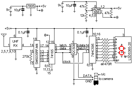
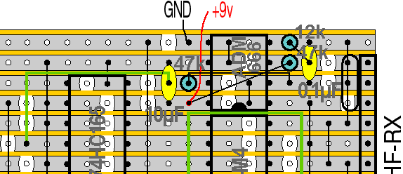
The circuit is more complicated than the first BASIC Stamp version. Since it is now using the smaller (and cheaper) 12C508, I had to add shift registers to handle the button inputs and LED outputs. Note there are two variants of the power supply - the ADM666 supports low battery detection, the 7805 doesn't.
The pre-built UHF receiver module outputs a bit stream to the decoder chip. The decoder chip looks for repeats of valid sequences. When it decides a valid data transmission has been received, it sets pin 17 (valid data) high and the data appears on pins 10-13.
The PIC is continuously in a main loop that performs the following actions, in sequence:
The input register takes in five bits, one for each button, plus a 'valid data' bit.
The PIC will do all this about 2500 times a second! To help eliminate spurious signals, the PIC will only accept a signal if it is the same 256 times in a row (i.e. ~0.1sec).
In particular, the PIC monitors the valid data bit from the decoder. As soon as it becomes high (1), the PIC knows that a remote button has been pressed.
The SM5035RF-M4 decoder and matching SM5023RF encoder support an eight-bit trinary encoding to distinguish different sets of receivers and transmitters. Each of the eight pins may be left floating, connected to ground, or connected to +5V for a total of 38 = 6561 codes. Leave all the pins floating until you have confirmed it working, then connect one or more pins to ground or +5V, making sure the transmitter and receiver are configured identically.
Note that the circuit diagram has my particular
LED display. Most likely yours
will be different - make sure you know the correct pinouts for your display! My
circuit is based on a common anode
LED display. If yours is common
cathode you will have to edit and re-assemble the source code. Change the
ledtype near the beginning from commonAnode to
commonCathode.
The sources given below are those most easily accessed in Australia. There are also (among others) RS Components and Farnell, but they are expensive and cater to industry rather than enthusiasts.
If you live outside Australia I can't help - I assume you know what's available in your area.
| Quantity | Description | Sources (you should confirm the catalogue numbers below before spending your money) | ||
|---|---|---|---|---|
| Altronics | Dick Smith Electronics | Jaycar | ||
| 1 | Veroboard (check to make sure there are no gaps in the tracks, such as for a model number or something - there must be 21×14 clear tracks) | H 0714 | H 5614 | HP-9540 |
| 1 | Microchip 12C508A PIC | Z 5005 | Z 9168 | ZZ-8602 |
| 1 | 74HC165 IC | Z 8665 | Z 5930 | ZZ-4858 |
| 1 | 74HC595 IC | Z 8924 | Z 5982 | ZZ-4895 |
| 1 | SM5035RF-M4 remote control decoder | Oatley Electronics (contact them - it's a non-catalog item) | ||
| 1 | 433MHz UHF receiver module | Oatley Electronics (RX14) | ||
| 1 | 2 pin header plug, straight | P 5492 | P 2731 (includes socket) | HM-3412 |
| 1 | 2 pin header socket | P 5472 | P 2731 (includes plug) | HM-3402 |
| 1 | 270k resistor | R 7075 | R 1134 | RR-0630 |
| 8 | 470R resistors | R 7042 | R 1066 | RR-0564 |
| 2 | 0.1µF capacitor, monolithic | R 2930 | R 2001 | RC-5490 |
| 1 | 10µF capacitor, tantalum | R 2638 | R 4750 | RZ-6648 |
| 1 | seven-segment LED display, common anode | Z 0191 | Z 4146 | ZD-1857 |
| 1 | 9V battery snap | P 0455 | S 6100 | PH-9232 |
| 1 | 9V battery | S 4930 | S 3286 | SB-2395 |
| 1 | Box, 85×56×40mm | n/a | H 2874 | n/a |
| 1 | switch, panel mount (for power) | S 2010 | P 7610 | SS-0852 |
| 1 | 2.5mm stereo plug (to connect to camera) | n/a | P 1127 | PP-0103 |
| 1-2m | cable, single core, screened (to connect receiver to camera) | W 3010 | W 2030 | WB-1500 |
| 1 | short length (30mm) of 10mm heatshrink tubing | W 0915 | W 4116 | WH-5535 |
| 1 | length of wire for antenna, preferably solid conductor (690mm full wave, 345mm half wave, 172.5mm quarter wave) | junk box | ||
| 1 | miscellaneous hook-up wire | junk box | ||
| 7805 Power Supply Variant | ||||
| 1 | 7805 5V voltage regulator, 100mA or better | Z 0460 | Z 6108 | ZV-1539 |
| ADM666 Power Supply Variant | ||||
| 1 | ADM666 or MAX666 5v voltage regulator | RS Components or Farnell | ||
| 1 | 12k resistor | R 7059 | R 0600 | RR-0598 |
| 2 | 47k resistors | R 7066 | R 0616 | RR-0612 |
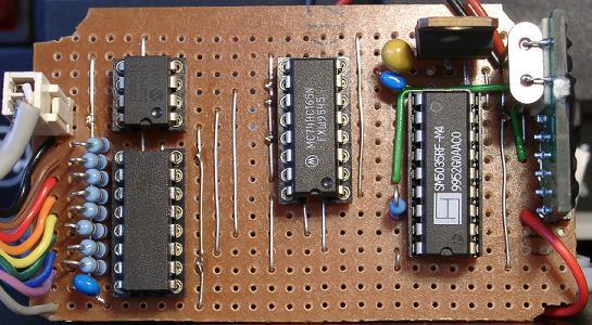
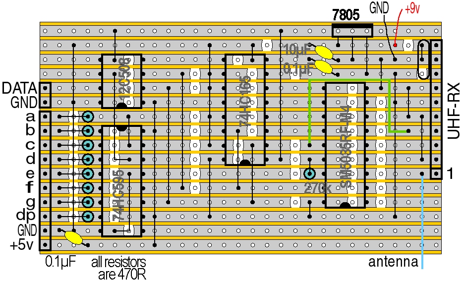
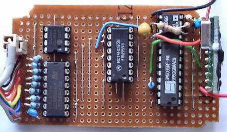
Refer to the photos and layout diagrams above while building to make sure you get things in the right spot.
Unless you are sure of your soldering and electronics skills, I would highly recommend the use of sockets for all ICs.
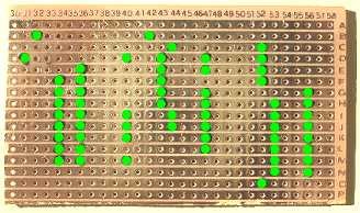
The receiver is built on 2.54mm (0.1") pitch veroboard, using 29×16 holes (75×42mm). The track strips are in the long direction of the board and need to be 'cut' as shown below. After marking each 'cut' with a felt-tip pen then double-checking the locations, I used a drill to remove the track layer. There are 61 'cuts' on the 7805 board (66 'cuts' on the ADM666 board - not shown):
First, install the eight 470R resistors, but keep the trimmed legs. The resistors are vertically mounted to minimise board space. If you're using IC sockets, don't put those in until after you've installed the links (next).
Now install the twenty bare links. Use the resistor legs you kept from the previous step for the bare links. The insulated link is put on after you've done the ICs.
Now do the seven 'T-links' (nine on the ADM666 board). These are the short links that provide extra connections from the bare links through to the solder side of the board.
If you're using IC sockets, now is a good time to install them.
Solder on the capacitors, power regulator (7805 or ADM666), and the remaining resistors (1 × 270k, 2 × 47k, 1 × 12k). Note that while I used a standard 1A 7805, this circuit will do just fine using a 100mA 78L05 regulator.
Put on the ICs. The 12C508 points down. The 74595 is immediately below it pointing up. The 74165 is in the middle pointing down and the SM5035RF-M4 is on the right pointing down.
You can put on the other insulated link now - bend it so it lies flat against the board and goes around the SM5035RF-M4 chip.
Solder the two-pin header at the far left of the board next to the PIC.
Now solder the LED display to the holes to the left of the resistors. From top to bottom, the segments are A through F, then the decimal point. The bottom two pins are a ground and 5V respectively (the 5V is at the very bottom). Connect the common of a common anode LED display to the 5V, the common of a common cathode display to the ground.
Solder on the UHF receiver module - the crystal is at the top.
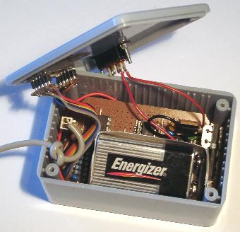
You can solder the battery connection to the board. I would recommend the panel switch be used so you can easily turn it on and off - particularly if you put the receiver inside a plastic box! The picture below shows how the board, battery, switch, and display fit in the box:
At this point, before you connect a battery, give your board a close examination, checking for bridged tracks or not-quite-soldered joints.
If possible, try to get access to a current-limiting 'laboratory' power supply and limit the current to ~50mA for testing. It's quite easy to 'blow up' the chips if you've made a mistake somewhere.
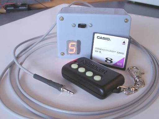
The picture below shows the finished remote control, including the key fob and a CF card for scale. The plastic shroud that came with the 2.5mm stereo plug fouled on the camera casing, so I threw the shroud away and covered the plug with some heatshrink tubing. Refer to the circuit diagram and board layout graphics for cable connections. Make the outside braid of the cable the ground and the inner core the data. The tip of the stereo plug has nothing connected to it.
Download the HEX dump of my PIC program, and program using your PIC programmer.
Happy remote controlling!
VALID»
Last updated: 2004-06-20. Copyright © 1999-2024.
http://www.scss.com.au/family/andrew/camera/remote/mk2/