Andrew Gregory's Web Pages
![]()
Rocky outcrop at sunset, Approx 27°56'15"S 119°38'17"E
I have modified the design since I originally posted this page so that the valid data output from the decoder chip is used by the Stamp to detect when valid data is present. This is to improve compatibility with other decoder chips you might want to use. For example, I have an infra-red remote control kit that uses a different decoder chip. Its outputs are maintained after the control button has been released, so the valid data output must be used to determine if a switch is actually pressed.
The changes to the Stamp program have made it about 40 bytes smaller too!
The remote control receiver is a custom design based on a pre-built 433MHz UHF radio receiver, a decoder chip and a BASIC Stamp. The Stamp is expensive, but easy to work with.
The receiver requires 8.5mA, plus 1.5mA for each LED (individual or segment) that is lit for a maximum of up to 23mA. In practice it is between 13 and 16mA. Pressing a button on the remote transmitter causes the receiver to consume an extra 0.2mA. In the 'power saving' mode the PBASIC 'nap' instruction is used in combination with turning all the LEDs off to reduce power consumption to 4mA. The battery should last about 30 hours of on-time.
The PBASIC program itself takes up 272 bytes, constant data 28 bytes, and it uses 4 bytes of RAM. Plenty of room (22 bytes of RAM and 1748 bytes of EEPROM) for enhancements...
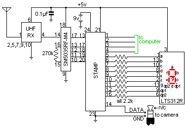
The circuit is very simple. The pre-built UHF receiver module outputs a bit stream to the decoder chip. The decoder chip looks for repeats of valid sequences. When it decides a valid data transmission has been received, it sets pin 17 (valid data) high and the data appears on pins 10-13.
The Stamp monitors the valid data bit from the decoder. As soon as it becomes high (1), the Stamp knows that a remote button has been pressed.
The SM5035RF-M4 decoder and matching SM5023RF encoder support an eight-bit trinary encoding to distinguish different sets of receivers and transmitters. Each of the eight pins may be left floating, connected to ground, or connected to +5v for a total of 38 = 6561 codes. Leave all the pins floating until you have confirmed it working, then connect one or more pins to ground or +5v, making sure the transmitter and receiver are configured identically.
Note that the circuit diagram has my particular LED display. Most likely yours will be different - make sure you know the correct pinouts for your display! My circuit is based on a common anode LED display. If yours is common cathode, see below for the changes required to make it work.
The sources given below are those most easily accessed in Australia. There are also (among others) RS Components and Farnell, but they are expensive and cater to industry rather than enthusiasts.
If you live outside Australia I can't help - I assume you know what's available in your area.
| Quantity | Description | Sources (you should confirm the catalogue numbers below before spending your money) | ||
|---|---|---|---|---|
| Altronics | Dick Smith Electronics | Jaycar | ||
| 1 | Veroboard (check to make sure there are no gaps in the tracks, such as for a model number or something - there must be 21×14 clear tracks) | H 0714 | H 5614 | HP-9540 |
| 1 | BS-2 IC BASIC Stamp | Z 5520 | K 1404 | XS-5530 |
| 1 | SM5035RF-M4 remote control decoder | Oatley Electronics (contact them - it's a non-catalog item) | ||
| 1 | 433MHz UHF receiver module | Oatley Electronics (RX14) | ||
| 1 | 24 pin IC socket suitable for Stamp | P 0570 | P 4240 | PI-6506 |
| 1 | 18 pin IC socket suitable for SM5035RF-M4 | P 0567 | P 4180 | PI-6503 |
| 1 | 4 pin header | P 5430 | P 2726 | n/a |
| 1 | 10 pin header plug, right angle | P 5520 | n/a | HM-3430 |
| 1 | 10 pin header socket | P 5480 | n/a | HM-3410 |
| 1 | 2 pin header plug, straight | P 5492 | P 2731 (includes socket) | HM-3412 |
| 1 | 2 pin header socket | P 5472 | P 2731 (includes plug) | HM-3402 |
| 1 | 270k resistor | R 0616 | R 1134 | RR-0630 |
| 9 | 2k2 resistors | R 0566 | R 1082 | RR-0580 |
| 1 | 0.1µF capacitor, monolithic | R 2930 | R 2001 | RC-5490 |
| 1 | seven-segment LED display, common anode | Z 0191 | n/a | ZD-1857 |
| 1 | 9V battery snap | P 0455 | S 6100 | PH-9232 |
| 1 | 9V battery | S 4930 | S 3286 | SB-2395 |
| 1 | switch, panel mount (for power) | S 2010 | P 7610 | SS-0852 |
| 1 | 2.5mm stereo plug (to connect to camera) | n/a | P 1127 | PP-0103 |
| 1-2m | cable, single core, screened (to connect receiver to camera) | W 3010 | W 2030 | WB-1500 |
| 1 | short length (30mm) of 10mm heatshrink tubing | W 0915 | W 4116 | WH-5535 |
| 1 | length of wire for antenna, preferably solid conductor (690mm full wave, 345mm half wave, 172.5mm quarter wave) | junk box | ||
| 1 | miscellaneous hook-up wire | junk box | ||
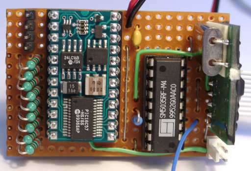
Refer to the photo and layout diagram below while building to make sure you get things in the right spot.
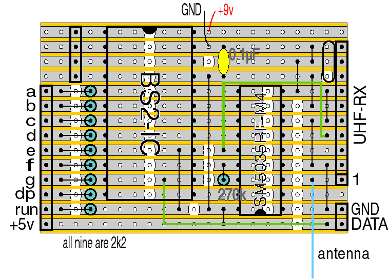
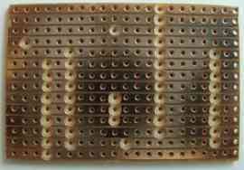
The receiver is built on 2.54mm (0.1") pitch veroboard, using 21×14 holes (55×37mm). The track strips are in the long direction of the board and need to be 'cut' as shown below. I used a drill to remove the track layer (there are 45 'cuts'):
Install the nine 2k2 resistors, but keep the trimmed legs. The resistors are vertically mounted to leave room for the Stamp socket to fit.
Now install the nine bare links and the bottom insulated link. Use the resistor legs you kept from the previous step for the bare links. The second insulated link is put on after you've done the IC sockets.
Put on the IC sockets - the notch of the Stamp socket points up, the other points down.
You can put on the other insulated link now - bend it so it lies flat against the board and goes around the 18-pin socket.
Solder on the four-pin header at the top left, leaving a gap between the it and the 24-pin socket to allow the cable connector room to fit on.
Solder the 270k resistor next to the 18-pin socket, and the 0.1µF capacitor up next to the 24-pin socket.
Solder the two-pin header at the bottom right of the board.
Turn the board over and solder the right angle 10 pin header plug with the pins facing into the board. The idea is to glue the socket it plugs into to the box you'll put the receiver in, then plugging the receiver into the socket also locates the receiver and stops it moving about.
Make up the 10 pin header socket so it connects to your 7-segment LED display. Arrange the wiring so that pins 5-11 of the Stamp are segments a-g, and pin 12 of the Stamp is the decimal point. My display has a second decimal point that connects to pin 16 of the Stamp. If yours doesn't have a second decimal point (most don't), connect a separate LED.
Solder on the UHF receiver module - the crystal is at the top, then install the ICs - make sure they point the right way! The Stamp points up and the decoder chip points down.
You can solder the battery connection to the board. I would recommend the panel switch be used so you can easily turn it on and off - particularly if you put the receiver inside a plastic box!
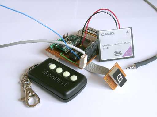
The picture below shows the remote board, including the key fob and a CF card for scale. The blue wire is the antenna. The grey cable leaving the photo on the left reenters at the top right to show the camera serial connector. The plastic shroud that came with the 2.5mm stereo plug fouled on the camera casing, so I threw the shroud away and covered the plug with some heatshrink tubing. Refer to the circuit diagram and board layout graphics for cable connections. Make the outside braid of the cable the ground and the inner core the data. The tip of the stereo plug has nothing connected to it.
At this point, before you connect a battery, give your board a close examination, checking for bridged tracks or not-quite-soldered joints. Use a multimeter to check the resistance across pins 23 and 24 and across pins 21 and 23 of the Stamp. Make sure they aren't short-circuited. Make sure none of the Stamp I/O pins (5-20) are shorted to either ground (pin 23 of the Stamp) or the power (pin 21 of the Stamp).
If possible, try to get access to a current-limiting 'laboratory' power supply and limit the current to 30-40mA for testing. It's quite easy to 'blow up' the chips if you've made a mistake somewhere.
I would recommend disconnecting the LEDs (if you've used the connector) and hooking up your multimeter to measure the current drawn by the receiver when testing. When the power is first applied it will briefly (<1sec) draw quite a bit of current before settling down to about 8-9mA. If you have left the LEDs connected and they're on it could be up to 25mA. If your multimeter measures more than 25mA for longer than a second, disconnect the power and look for what the problem might be.
Now that it's built - you have just to program it. Below is a diagram of the serial connection:
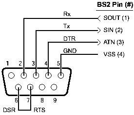
You can either make a special cable that goes between the Stamp and your computer, or you could solder a temporary DB9 connector directly to the board (you wouldn't need the four-pin header then).
The Stamp programming software
can
be downloaded from the Parallax
web site. I would suggest using the Windows program (STAMPW.EXE).
Power up the receiver board and run the software. Select the 'Identify' option from the 'Run' menu. It should display a dialog showing the type of Stamp you have. If not, check your cable, serial settings, etc.
Assuming 'Identify' works, download my PBASIC program:
Load the source into the Stamp software, then select 'Run' from the 'Run' menu. The program will be compiled and downloaded to the Stamp and will automatically start running. All the LEDs should turn on briefly before an 'S' appears. The 'Run' LED will also start blinking. Don't connect it to the camera just yet - make sure that pressing buttons on the remote transmitter makes the receiver do things. Then you can connect it to the camera.
Happy remote controlling!
You can use a common cathode LED display if you make the following changes:
ledType
constant to commonCathode. It's under the
'LED control' section near
the start of the listing.Connecting an LCD display probably wouldn't be too much trouble. Just replace the current limiting resistors with links and connect direct to the LCD (it will also need a ground connection). The 'one wire' LCD from Parallax would make things really simple. There is no problem powering the display from the Stamp - even the backlight (which could be under Stamp control too)!
The real problem is that it would require substantial modifications to the
PBASIC program. It is left as an exercise for the reader
![]() .
.
In theory the Stamp could be set up to have the camera take a sequence of photos at intervals. In practice, the seven-segment LED display is too limited to allow input of all the various required options. Besides, I have my QVRemote program on my PDA for that sort of thing. The previously mentioned LCD display would be perfect for this task.
A slight problem is the resonator on the Stamp - it isn't very accurate. A good crystal based clock generator, divided down to 2Hz would make it easy for the PBASIC program to poll and keep good time.
Extra displays could be added, probably about two more would be the limit before the power requirements would demand a separate regulator. In fact three would probably be enough to implement the time lapse function.
There aren't enough Stamp pins to directly control three LEDs, so they would have to be connected serially using latching shift registers. Three Stamp pins could handle any number of displays!
An alternative to big displays to handle time lapse photos would be to use a PDA to program the time lapse settings via a serial link. The settings can be stored in the EEPROM. Ignoring timing considerations, the current design of the board has two spare pins that could be used for receive/transmit signals.
A really cool idea would be to use two stepper motors to tilt and pan the camera. The Stamp programming manual shows how to interface a stepper motor using 2 outputs per motor. An excellent combination would be the UHF TV transmitter kit from Oatley Electronics (K151) and a handheld LCD TV!
VALID»
Last updated: 2004-10-22. Copyright © 1999-2024.
http://www.scss.com.au/family/andrew/camera/remote/mk1/