Andrew Gregory's Web Pages
![]()
Guilderton Lighthouse 30°20'24"S 115°29'31"E
I got bitten by the GPS bug after my Dad got himself a GPS 12XL from Garmin. Although the Garmin works very well, I thought the small display and simple keypad could be improved and I could do a much better job hooking up the GPS to my Psion!
As you can see below, I've built a working GPS unit, but I have yet to write a single line of code to talk to it! I just don't have the time. For now, it is connected on a permanent basis to my Linux server using a special cable I made that also powers the GPS unit from the server.
Having it connected all the time means that the Linux server is always within a second of correct time, and so are all the workstations (four) connected to it.
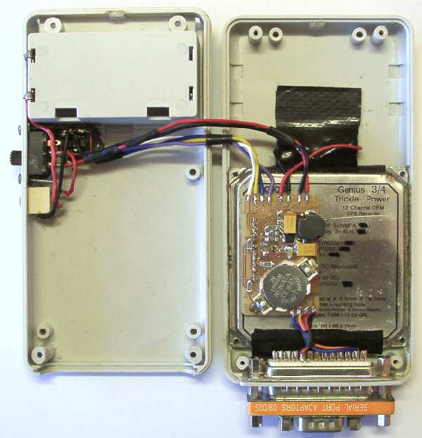
The GPS receiver I ended up buying cost nearly as much as the Garmin. The Rojone Genius 3 is an integrated receiver, combining a patch antenna and processor to produce a standard NMEA RS-232 output. The complete receiver is shown below connected to my 3mx. It would just as easily connect to my MC218.
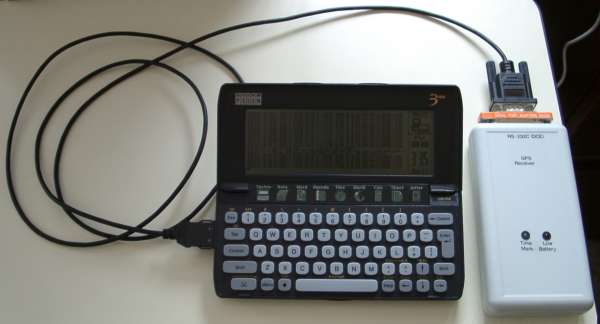
It's a very compact unit, fitting inside a 135×70×24mm case from Dick Smith Electronics (H-2949). The case even comes with a battery compartment and terminals for two AA batteries! The receiver is 65mm square and I had to grind out the inside of the case a little so it could fit. Everything fits inside the case: GPS receiver, power supply board, batteries, on/off switch, external power socket, backup battery, LEDs (time mark (pulse-per-second) and low battery), and configuration DIP switches. It's a bit of a squeeze!
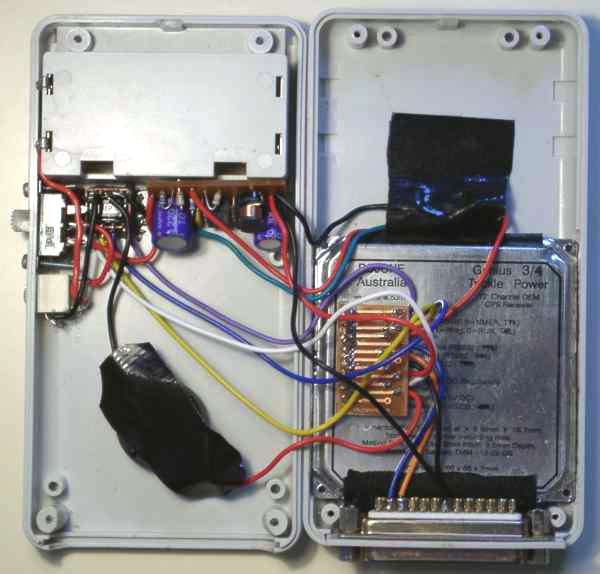
At the top left is the battery compartment. Immediately below that from left to right are the on/off switch, DIP switches (all you can see is the back - they poke out a hole in the bottom so that they can be changed without opening the case), and power supply board.
Below the on/off switch is the external power socket. It automatically disconnects the batteries and connects to the power supply board inputs. This allows the external power to be anything between 2 and 5 volts as the power supply will step-up and regulate as needed.
The black object below all of these is the backup battery. It is a CR2025 inside a battery holder. The black stuff is tape insulating the battery connections from the GPS receiver.
On the right side at the top is more black tape. This covers and insulates the two LEDs. Below that is the GPS receiver (underside). The antenna is the top (hidden) face of the receiver. The brown board on the receiver connects the various wires to the receiver.
Below the receiver is a regular DB25 serial connector, wired up so that I can directly connect my Psion with a slim-line DE9-DB25 adaptor.
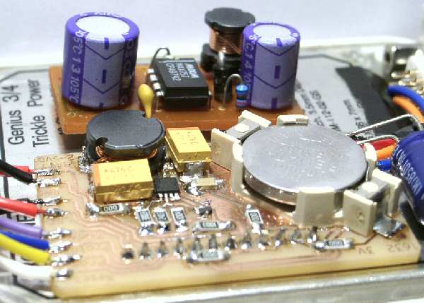
I had to design and build a switch-mode power supply so the 5V GPS can work from 3V batteries. A friend of mine designed and etched the custom PCB. In the picture below you can see red/black wires from the batteries on the left, red/green wires in the centre going to the low battery LED, and red/black/black wires going to the GPS receiver. It's all pretty much looked after by the MAX757 chip (made by Maxim).
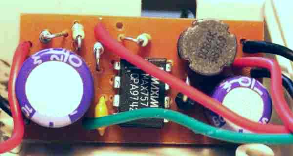
The power supply is reasonably efficient, generally above 85%. The Rojone design incorporates a special trickle-power mode (as opposed to a continuous power mode) that greatly extends battery life. I typically have the receiver sending NMEA RMC messages every two seconds and NMEA GSA/GSV messages once every minute. In trickle power mode the batteries last for about 9.5 hours. In continuous power mode they last about 2 hours.
The only down side is when the batteries fail - the power supply draws more and more current attempting to power the GPS receiver, and the batteries get very hot!
![]() GPS Receiver Design
Document (18969)
GPS Receiver Design
Document (18969)
In June 2005 I purchased a new Treo 650 which supports Bluetooth. Not long after I purchased an Aircable Bluetooth Serial adapter with the intention to use it for both telescope control and this GPS.
The problem was the power supply as detailed above was only designed to supply up to 200mA. I expected the total of the GPS and Bluetooth adapter to require at least 250mA. So a new power supply design was required. The best power supply chip I could find for the job was the MAX1797, able to supply (in theory) up to 300mA at my desired low battery cut-off of 1.8V (which I've since revised to 2.0V to cater for the slightly higher cut-off for NiMH cells compared to alkalines). It's a surface-mount chip, so I decided to go fully surface-mount for the whole thing. It has True-Shutdown™, which disconnects the load from the power supply when the battery voltage falls below a threshold. My old power supply couldn't do that, which would result in the batteries being fully discharged - making them extremely hot, and destructive to rechargable cells.
I also found an application note for a low-battery hysteresis circuit. When the shutdown facility disconnects the batteries, they immediately recover some voltage - enough for the shutdown to reconnect the batteries unless the turn-on threshold is made higher than the turn-off threshold. The result would be the power supply switching off and on - probably not too good for the GPS! Adding some hysteresis allows the batteries to recover without switching the supply back on. Locating a MOSFET suitable for the low voltages involved took some doing, but with some assistance (thanks David!) I found one (SI1032R).
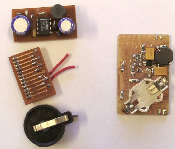
After obtaining the MAX1797 and related capacitors and inductors, I realized that the whole circuit would be 5mm high (the first one was 14mm high), and therefore would fit underneath the GPS module. That meant that I would be able to combine the previous three components - power supply board, GPS interface board, and backup battery holder - into a single board. A single-sided design would mean no worries about things shorting on the metal GPS body. A much more neat and tidy inside!
I designed the PCB and got a friend to etch it. Then I spent an entire afternoon squinting and generally ruining my eyesight, not to mention testing my patience, putting it all together.
Out with the old, in with the new!
The inside of the enclosure is so much better looking now!
You can see how the new PSU has a much lower profile than the old one.
The only thing missing is the low battery indication, which I totally forgot about! It's probably not a big deal - the Bluetooth module has its own LED, so that can act as a power-on indication. The GPS still has its time-mark LED too. The new shutdown facility means I don't need to worry about the batteries either.
The only other item of note is that testing of the unit at low battery inputs and full power output (250mA), resulted in huge 2V peak-to-peak ripple! That's currently been resolved by adding a 100µF cap on the output, but I suspect it has created some low battery startup problems. Testing is continuing.
VALID»
Last updated: 2007-07-20. Copyright © 1999-2024.
http://www.scss.com.au/family/andrew/gps/rojone/