Andrew Gregory's Web Pages
![]()
Rocky outcrop, 28°30'11"S 122°46'31"E
I've always been curious as to what was inside my camera, but not so much as to actually undo the screws and look. Finally, from icy Russia, someone brave enough to open up their expensive QV-3000 digital camera and take pictures!
The information on this page is based on the pages originally put up by "Vladimir Rodionov" <rwpbb at ixbt dot com>. It is with the kind permission of Vladimir that I am able to provide this page with his original images.
It would seem that he was mostly interested in finding out how strong the casing of the camera would be in order to attach an extra lens. Along the way he took many interesting photographs and did some analysis of the parts inside! You can find his original pages (in Russian) at:
What follows are my comments based on a machine translation of his pages and my own thoughts.
An owner of a QV-3500, who goes by the pseudonym of ""Freycinet" <webtelefoni at hotmail dot com>", had to have his camera serviced to fix the well known flash problem. He took some photos while it was opened up. You can visit his web page at http://www.iue.it/Personal/Researchers/Dalsgaard/.
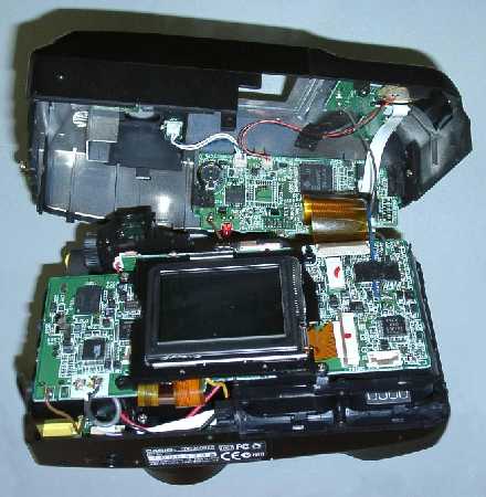
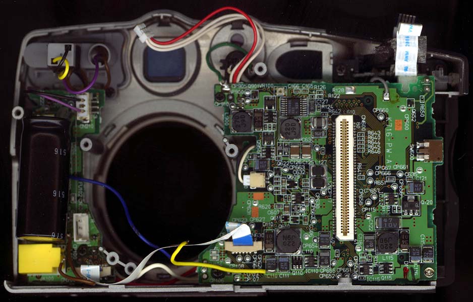
This photo from Freycinet, shows the camera mostly intact, with the circuit boards still installed:
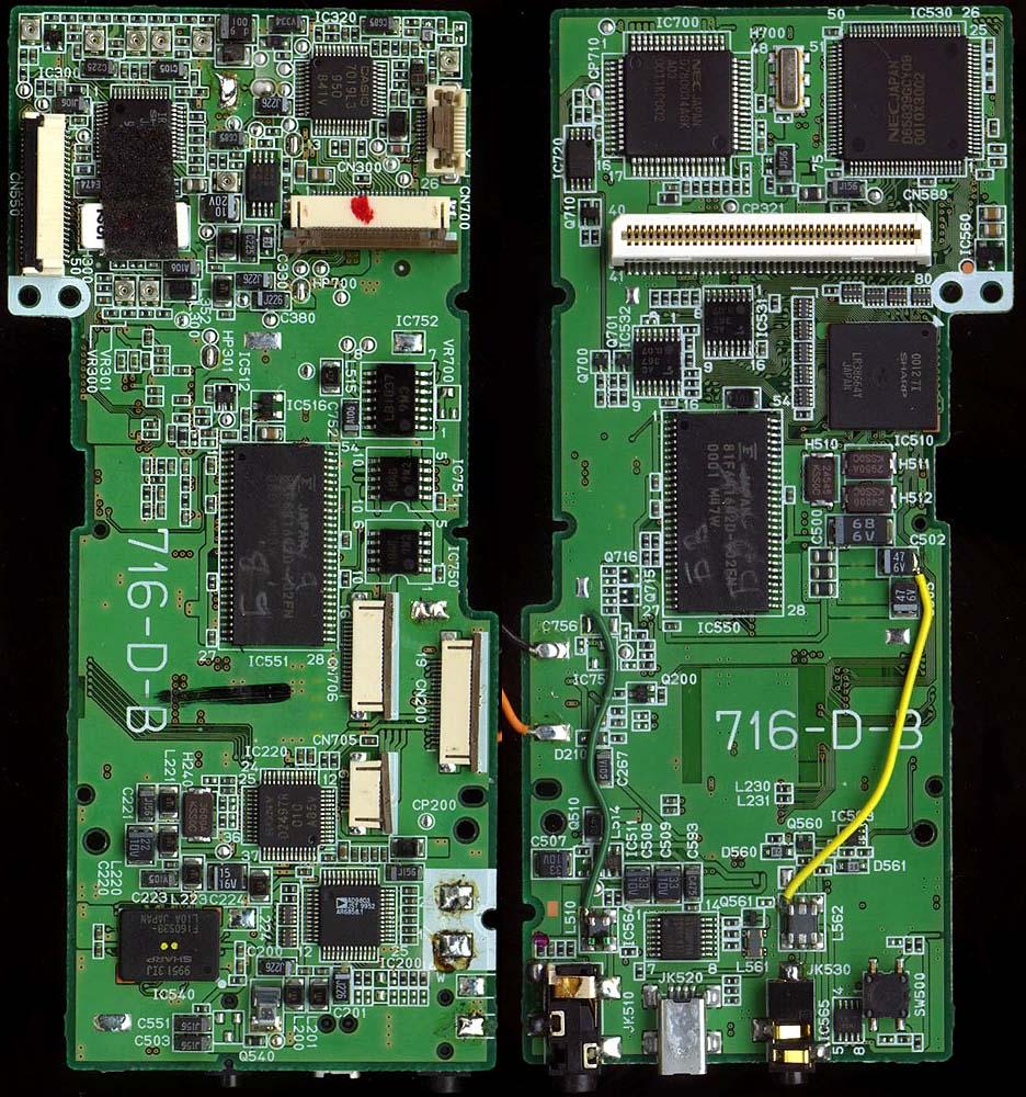
These photos by Vladimir show some of the individual boards:
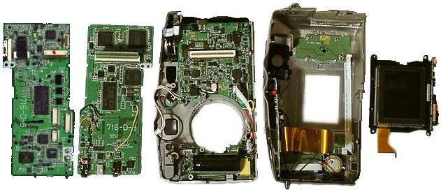
Photos of:
Main circuit board and
Front assembly
From left to right they are:
The main circuit board has components on both sides (see them close up). You can tell the second image is the side that faces the front because it has the connector that lines up with the connector on the very front board in the third image. It includes the connectors for the video out, USB, and serial communications. The large black integrated circuits in the middle of the front and back sides of the board are most likely the camera's RAM, probably 16MB each for a total of 32MB.
The front assembly (see it close up) has a circuit board on one side. The DC connector and the flash charge capacitor (the big black component at the bottom) are on the other side. Vladimir found that the capacitor was 180µF at 330V.
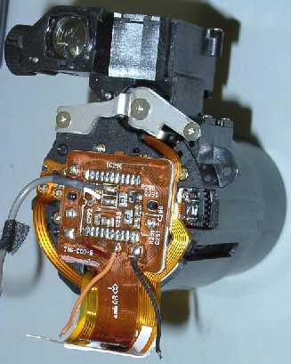
It has been reported that the faulty flash experienced by many early buyers of the QV-3000 was due to a 'cold' solder joint on a PCB. The PCB is the one just below the flash housing and behind the large capacitor in the front assembly. Freycinet took the following close-up photo of it. Hearsay has the bad solder joints to be around the square black component to the middle left.
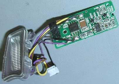
You'll also notice the odd stray wire joining parts of the PCBs. These are either to carry higher current than regular PCB traces or the flexible orange-brown strips, or they rectify faults found after the boards were manufactured. Having worked in the electronics industry, I know how easy this can be. One missed 'via' (a hole with a conductive filler that joins tracks on different sides of a PCB) and extra fixup wires have to appear! Pity the poor sods who have to fix the boards by hand.
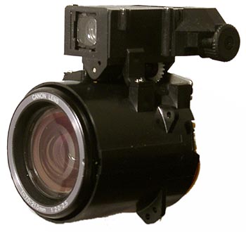
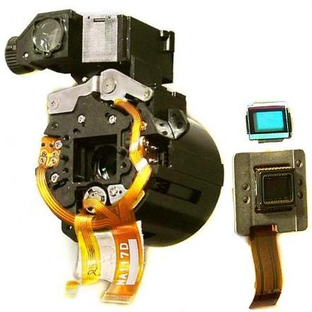
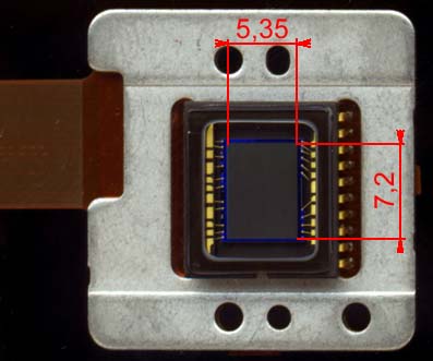
The above photos by Vladimir are two views of the camera lens assembly, the blue infra-red/ultra-violet filter, and the CCD assembly. Some other cameras are suspected of using this same lens assembly:
The photo below by Freycinet shows the lens assembly with the CCD still attached:
The camera lens and viewfinder are linked so as you zoom in and out, both the CCD view and your eye view are synchronised. The purpose of the blue filter is less clear. Why should you filter out light you can't see? CCDs are sensitive not only to visible light, but also to infra-red. However, the CCD only outputs RGB data. If the infra-red wasn't filtered out, it would become part of the RGB data and therefore become visible in the resulting pictures (see also link below showing that sensitivity to IR light can blur the image). This means that the photos you take would look different from the world you see. The blue filter greatly reduces the infra-red seen by the CCD, making the CCD behave much more like your own eyes, and the resulting pictures much closer to what you see.
The IR/UV filter is coloured blue because it also filters out some visible red light, as the spectrum analysis below shows:
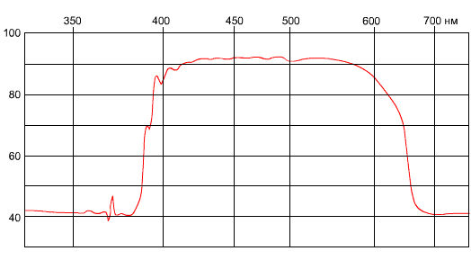
The horizonal scale is the wavelength of the light in nanometres. The vertical scale is probably the percentage of light let through the filter at the given wavelength. The visible spectrum starts at about 390nm for violet light and extends off the edge of the graph to 780nm for red light. As you can see, while the filter has a steep slope at about 390nm, the other slope is at about 650nm, well before the 780nm for red light.
So, why don't all the photos turn out blue? It would have to be a combination of one or more of the following:
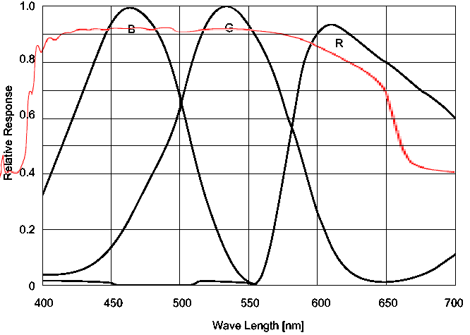
Below is the spectral response of the CCD used in the Casio, the red line is the IR filter:
Some links to CCD spectral response graphs are below:
![]() Sony ICX252AQ Data Sheet ( 413K)
Sony ICX252AQ Data Sheet ( 413K)
The CCD used by the QV-3000 is part number ICX252AQ manufactured by Sony. The imaging element measures 7.2mm × 5.35mm and has 2140 × 1560 sensor elements, but an effective size of 2088 × 1550 sensor elements. Of course, the QV-3000 only keeps 2048 × 1536 of those. The extra unused elements may be useful to allow some differences in manufacturing and alignment of the lens and CCD assemblies. They may also be used by the firmware to aid in improving image quality (I'm not sure how, though).
It appears to be a Sony internal part, not manufactured for general sale. It is suspected that it is also used in the following digital cameras:
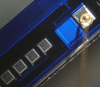
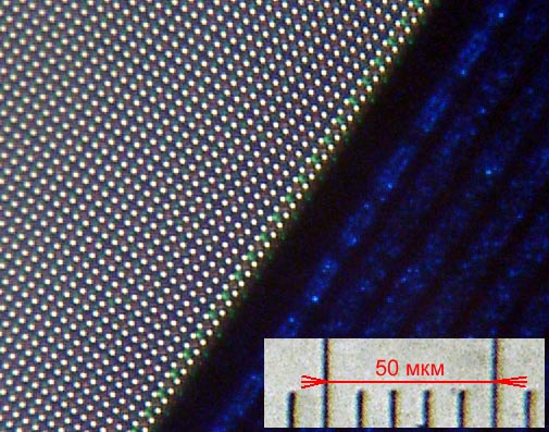
These close up pictures of the CCD show it's construction. Looking closely at the second more highly magnified view of the CCD reveals a pattern to the image sensors:
![]()
Each different colour is a different pixel on the CCD. In other words, out of the total 3145728 (2048 × 1536) pixels used on the CCD, 1572864 are green, 786432 are red, and 786432 are blue. The camera is able to turn them into 2048 × 1536 individually coloured pixels. How Stuff Works explains how.
Digital Photography Review published the following specifications of the ICX252AQ:
| CCD Size | 8.93mm (~1/2") diagonally |
|---|---|
| Form | Interlaced |
| Effective pixels | 3,240,000 (2088 × 1550) |
| Total pixels | 3,340,000 (2140 × 1560) |
| Cell size | 3.45µm × 3.45µm |
| Colour filter | Primary RGBG |
| Max horizontal driving frequency | 18MHz |
| Frame rate | 4.28fps |
| Sensor saturation level | 450mV |
| Sensitivity (F5.6) | 270mV |
| Signal to noise ratio | -94dB |
| External size | 13.8mm (W) × 12.0mm (H) × 2.9mm (D) |
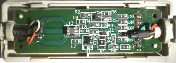
I got curious about what was inside the small box on the Casio serial cable that came with the camera, so I popped it open and took photos!
Below is the top of the PCB. It's not very exciting as all the components are surface-mount and on the bottom of the PCB. The white blocks are where the cable wires connect to the PCB.
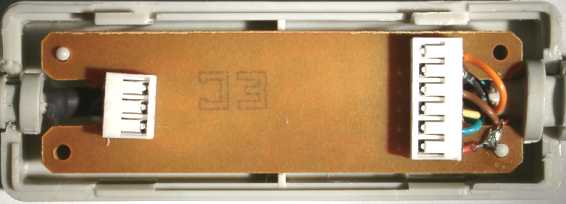
Below is the bottom of the PCB. This is where all the components are - they appear to be soldered on by hand! They are all passive components - resistors, transistors, and diodes - no ICs. The circuit is a patented design by Larry Buerg.
Casio appear to use the same cable for many of their other devices, such as organisers and calculators. Some of the sites below refer to cables for these devices, but should also work fine for Casio digital cameras (including the QV-3000EX):
VALID»
Last updated: 2005-07-12. Copyright © 1999-2024.
http://www.scss.com.au/family/andrew/camera/inside/