Andrew Gregory's Web Pages
![]()
Rocky outcrop at sunset, Approx 27°56'15"S 119°38'17"E
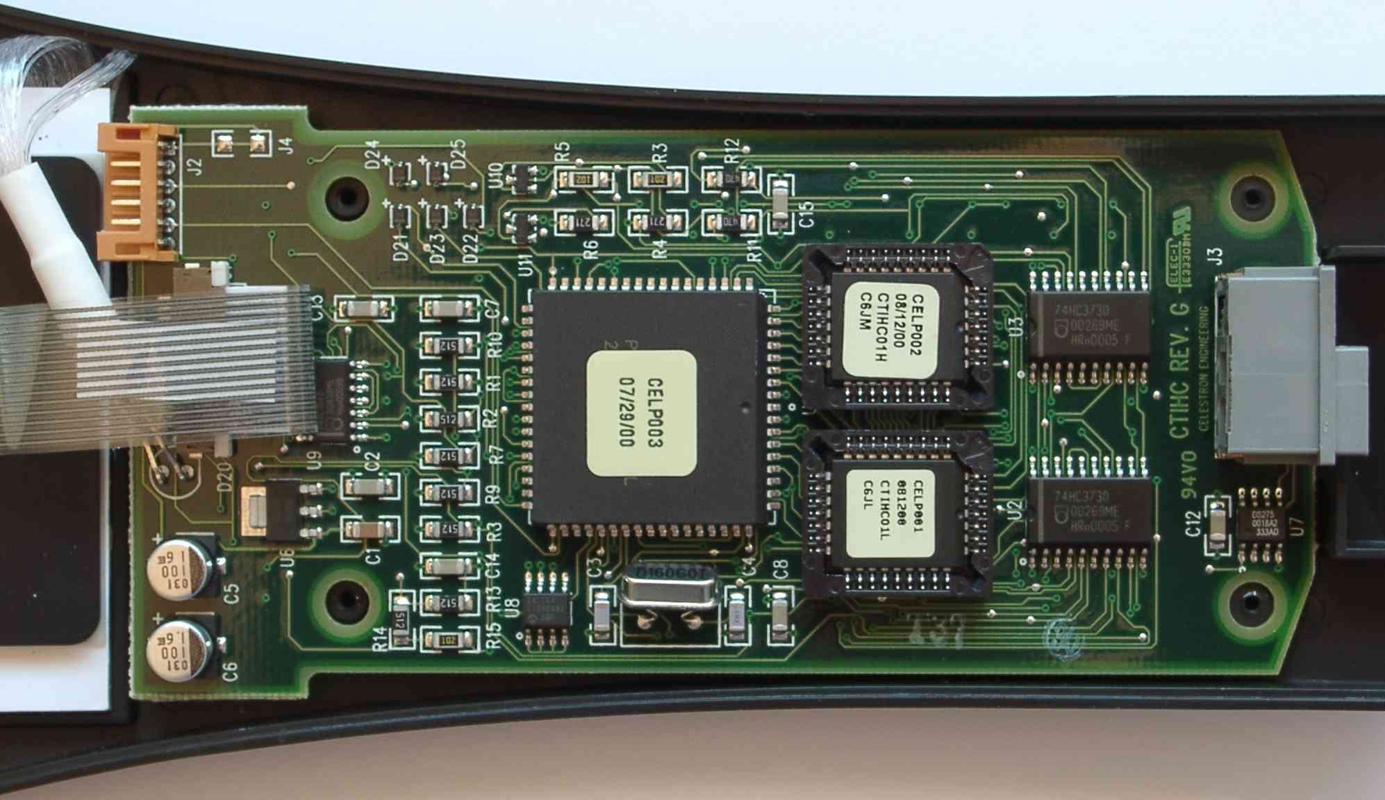
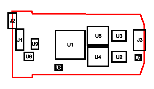
The 17C752 is the main microcontroller. The AT27C010's most likely contain the firmware. The firmware program is stored in 16-bit words. The labels indicate that the low byte of each word is stored in U4 and the high word in U5. It's possible there could be more firmware stored inside U1.
Note that the AT27C010's are 128K×8, while the 17C752 can only address 64K×8. It might appear that only half of the storage in the ICs is used, but the A16 line is controlled by the 17C752 via RG0 (pin 34).
There is the possibility that the entire firmware is contained within the EPROM ICs. That means it's possible to reverse engineer the firmware, or simply to replace it! The current firmware I have certainly needs replacing!
On the other hand, the 17C752 might contain the first 8K of firmware, with the remainder on the AT27C010's. This should be able to be determined by dumping the AT27C010's and seeing if there is any code in the first 8K (if the on-PIC program memory is used, the corresponding external EPROM memory cannot be used). Using the onboard program memory would certainly make switching 'banks' via RG0 a lot easier, but it would also make it impossible to make any changes to the internal firmware.
The 24LC64 stores whatever settings need to be kept when the power is off (such as the telescope model, locations, etc). 8K seems like a lot of storage.
The 74164 interfaces to the LCD, allowing the 17C752 to use a reduced number of pins to communicate with the LCD. The LCD itself most likely has one of the standard Hitachi LCD microcontrollers to manage the technicalities of the display, so that the 17C752 just has to send relatively high-level display commands to it.
The white tube at the left of the PCB, has a waterclear red LED going in at the bottom, and a bundle of glass optic fibres going to the LCD display. This obviously provides the red backlighting to the LCD display.
The other side of the PCB just has a small surface-mount LED for each button, plus pads for telling when a key is pressed.
I've traced many of the control line to the PIC, here are some notes:
From the above, the port usages are (Misc=Keys/Unused):
Total "Misc" pins is 19, which equals the number of buttons. When I had my controller open, I noticed that at least some of the keys made contact with two pad pairs. This could mean the keypad is encoded by row-column, perhaps 5×4 which would only require 9 pins (instead of 19). I don't know how the faster slewing by holding down two direction keys at once would fit into this.
Vincent Sanders has opened up the mount of his Celestron NexStar 114GT refracting telescope. See his pages for full details.
Since the GT hand controller is the same for both telescopes (and the 'Custom' configuration numbers are also the same (1059334), I would expect his 114GT and my N4 to be the same.
VALID»
Last updated: 2013-03-11. Copyright © 1999-2024.
http://www.scss.com.au/family/andrew/astro/inside/