Andrew Gregory's Web Pages
![]()
View from Snake Hill, Lake Ballard, 29°26'40"S 120°36'19"E
When I bought my Treo 650 my chosen astronomy software was Astromist. Part of the benefit of buying it was getting a good deal from Aircable on their Bluetooth serial adapter.
Being able to control my telescope from my PDA was something I'd wanted to do for a while, but I'd had trouble finding planetarium-type software that would also control my telescope. Astromist and the Aircable were the answer.
I was able to quickly confirm they would work by rigging up a messy set of adapters, cables and batteries. Ultimately, I wanted to be able to power the Aircable from the telescope batteries (the Aircable accepts 5-15V, the telescope runs on 8-12V), and try to mount things so they wouldn't get in the way of using the telescope.
What I ended up being able to do was build an adapter that enabled me to fit everything behind where the handcontroller sits in the telescope mount arm. From the outside, you can't tell the telescope has been Bluetooth-enabled!
The first step was to figure out the various connections. First the handcontroller mount connection:
| Pin | Handcontroller Wire Colour | Function | |
|---|---|---|---|
 |
1 | Blue | Ground |
| 2 | Yellow | Ground | |
| 3 | Green | Transmit (CMOS/TTL) to telescope base | |
| 4 | Red | +12VDC (batteries) | |
| 5 | Black | Receive (CMOS/TTL) from telescope base | |
| 6 | White | Ground | |
Then the handcontroller serial port:
| Pin | Function | |
|---|---|---|
 |
1 | Receive (RS-232) into handcontroller |
| 2 | Ground | |
| 3 | Ground | |
| 4 | Transmit (RS-232) from handcontroller | |
Then the Aircable (mine is female, designed to be connected directly to the PC):
| Pin | Direction (from Aircable) | Function | |
|---|---|---|---|
 |
1 | Out | CD (Carrier Detect) |
| 2 | Out | Rx (Receive Data) | |
| 3 | In | Tx (Transmit Data) | |
| 4 | In | DTR (Data Terminal Ready) | |
| 5 | - | Ground | |
| 6 | Out | DSR (Data Set Ready) | |
| 7 | In | RTS (Request To Send) | |
| 8 | Out | CTS (Clear To Send) | |
| 9 | In | Power (5-15VDC) | |
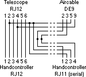
The next step was to create a wiring diagram to fit the various pinouts together:
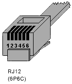
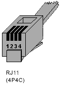
Construction was fairly straightforward. I bought a PCB mount top-entry 6P6C RJ12 socket, a flat ribbon DE9 connector (to save space), a 6P6C RJ12 plug and a 4P4C RJ11 plug. You'll need a modular crimping tool for the plugs.
One gotcha (that got me!) is the order of the conductors in the ribbon cable from the DE9 connector. They are, of course, interleaved across the cable: 1, 6, 2, 7, 3, 8, 4, 9, 5.
To help hold wires together for soldering, I used narrow-diameter heatshrink tubing to "clamp" two or more wires together, soldered them, then slipped a second bit of heatshrink over the end to insulate it.
Finally, a couple of ties hold everything together and provide a bit of strain relief.
Trivia: All photos were taken using my Treo 650.
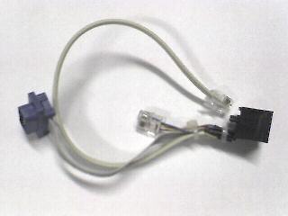
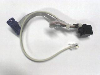
The adapter by itself:
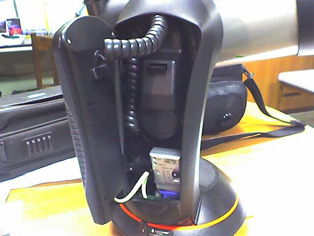
The complete installation, with the handcontroller connected and Aircable in place:
VALID»
Last updated: 2007-07-20. Copyright © 1999-2024.
http://www.scss.com.au/family/andrew/astro/adapter/